My Japanese Fender electric/acoustic fretless bass is a wonderful instrument, but the piezo pickup lacks low-end punch. Some inspection of the internal electronics reveal the reason: the piezo directly drives the pot that mixes the two pickups together; the output of the pot then goes to the active electronics. This means that the piezo pickup is seeing a best-case impedance of about 250k, and a worst-case (when the log-taper pot is in the middle position) impedance of about 5k. It should be seeing at least 1M to be really happy. Here's what the factory active electronics look like. (Note: as of 12/2000, I've fixed some bugs in this schematic. I hope no one was too misled.)
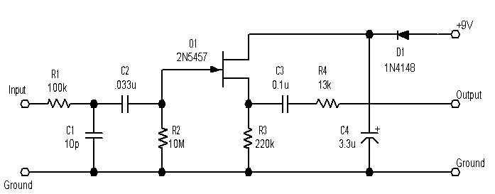
So, I built this little pre-preamp, that goes between the pickup and the pot. It's unity gain, but because the pickup is loaded less it puts out more, so it actually causes a bit of volume boost. The bass sound is much, much better: I can now just use the piezo pickup alone if I want.
Please note: some folks have asked me about using this as a preamp to drive an amp, that is, as a replacement for the active electronics in their bass. I don't recommend it. This circuit is not intended to drive a long cable, it's just a buffer between the piezo pickup and the rest of the active electronics within the bass itself.
I live near radio towers, so the circuit is designed to be fairly RF-proof, a challenge with high impedances. I soldered the shielded cable from the pickup directly onto the preamp circuit board, and also took a shielded cable from the output to the pot. The 10pf capacitor and the ferrite bead also help here.
The output resistor keeps it from distorting when the mix pot is in its midrange position. Without it, the 5k load is a bit too much for this simple FET circuit to happily drive. If I did it again, I might add a second, bipolar emitter-follower stage: when I first designed it, I didn't realize the load would get that low. Or more likely I'll just replace the electronics altogether.
I built this on a double-sided PC board which I hand-etched with a Dremel tool following this pattern. I used double-sided so that I could get a good ground plane. The circuit is on the solder side; the component side is just ground plane. Here's a picture of the unit and a picture of how it sits in the cavity.
LATEST NEWS: I replaced my magnetic pickups with Lane Poor P-style pickups. They're not quite as hot as the Lace pickups, so I increased the output resistor to 220k; it still isn't quite the right balance, so some more work is required. But the LP's sure sound great. Also, I notice that Bartolini sells a preamp that's intended for piezo/magnetic combos; I've not tried it, but I'd love to hear from anyone who has.
